


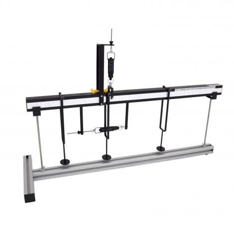
Bending Moment Diagram
Technical Description:
This consists of a beam mounted on two supports which is subjected to point loads. The beam is cut at one point. At that point there is a low-friction hinge with one degree of freedom. The bending moment occurring at the section is recorded by a force gauge acting on a fixed lever arm. An adjuster nut on the force gauge is used to align the beam horizontally and balance out any lowering. The reactions are determined from the static conditions of equilibrium. To investigate the effect of the point loads in the beam, it is notionally split into two segments. Applying the method of sections, the internal forces and moments are plotted onto the two segments and calculated by way of conditions of equilibrium.
Specification:
1. Investigation of bending moment on beam mounted on 2 supports
2. Indication of bending moment in beam by low-friction hinge with 1 degree of freedom
3. Position of hinge at 1/3 span
4. 2 bearing supports
5. Loading of beam by 1 to 3 point loads
6. Force gauge and lever arm to indicate bending moment
7. Adjuster nut for horizontal alignment of beam
8. Storage system to house the components
Technical Detail:
Beam
– total length: 1000mm, span: 800mm
Bending moment measuring range: -10…+10Nm
Weight set
– 3x 1N (hangers), 12x 1N, 9x 5N
– max. weight load per hanger: 20N



Reviews
There are no reviews yet.